General
A logic constraint in Dax Phyz performs a well-defined, simple operation, such as adding two numbers and storing the result in a register.
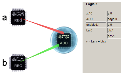
Each logic constraint has an internal register called v (for value) which can store a 32-bit floating point number. The ADD logic above will continuously add the contents of the connected REG logic v registers, and store the result in its own v register.
A logic constraint added with the Logic tool in Dax Phyz has its internal enabled flag set to 0 (false) by default, which means it is passive and doesnt perform any operation. To enable it, select it and change enabled to 1. Note that some logics, such as the REG logic, are inherently passive and thus arent affected by the enabled flag.
Synchronized logics
Edge triggered logics
By default, a Dax Phyz logic constraint is asynchronous, continuously and repeatedly performing its operation as quickly as possible (as long as it is enabled).
By setting a logics edge register to 1, its operation is performed exactly once at the start of every physics frame.
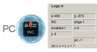
The INC logic above will increase its own v register once every physic frame (125 pps in Low speed). Note how its L connector points to itself.
PC triggered logics
In many cases its desirable to control the order in which different logic operations are performed. For instance, to calculate (a+b)*c, we would need to complete the addition before the multiplication, or the result would be undefined in most cases. To accomplish ordered execution of logic operations, a program counter (PC) can be utilized. The idea is to tell Dax Phyz to execute the operation of a particular logic when, and only when, the value of the PC equals a specific integer, specified in the logics edge register. The PC is specified in the logics pc register, which equals -1 (unspecified) by default.
Both edge triggered and PC triggered logics have edge!=0, but only PC triggered logics have their PC point to a logic. Edge triggered logics have their PC=-1.
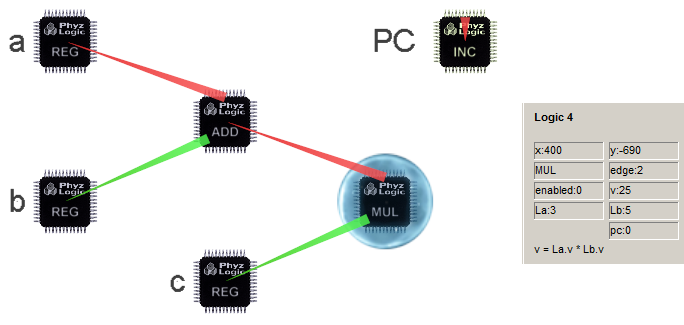
Above, the PC is logic number 0, which is specified in both the ADD and the MUL logics. The ADD logic has edge=1 and the MUL logic has edge=2, indicating that they will execute when PC equals 1 and 2 respectively.
Usually, the PC logic is an edge triggered INC pointing to itself, so that its value is increased by 1 every physics frame.
Loops
In the example above, the PC value will increase from its default value 0. When it reaches 1, the ADD logic will perform its operation. At 2, the MUL logic will execute. After that, the PC will continue to increase its value eternally, never again triggering neither ADD nor MUL. To perform the combined add-then-multiply program repeatedly, we could alter the contents of the PC value with a CPY logic, which copies the contents of one v register to another v register.
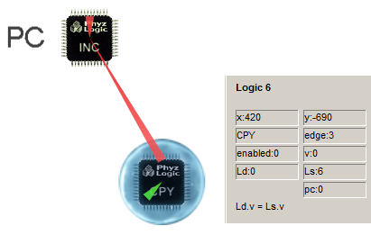
The CPY logic copies its own value 0 to PC every time PC equals 3 (since the CPY has edge=3 and pc=0). This creates a loop, with PC taking on the values 0, 1, 2, 3, 0, 1, 2, ... indefinitely.
Conditional flow
By replacing the CPY logic with CPYIF, we can control program flow conditionally. The CPYIF logic acts as CPY, but only when the value of an additional logic Lb has a value other than 0 (false).
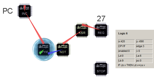
Above, CPYIF checks if the Escape key (key code 27) is depressed. If it is, no copy is performed, causing PC to reach 4, triggering the STOP logic (edge=4, pc=0), which stops physics simulation in Dax Phyz.
The KSR logic is edge triggered (edge=1, pc=-1), reading the state of the Escape key at the beginning of every physics frame. The NOT logic is asynchronous (edge=0, pc=-1), continuously updating its value to 0 if KSR is 1 and vice versa.